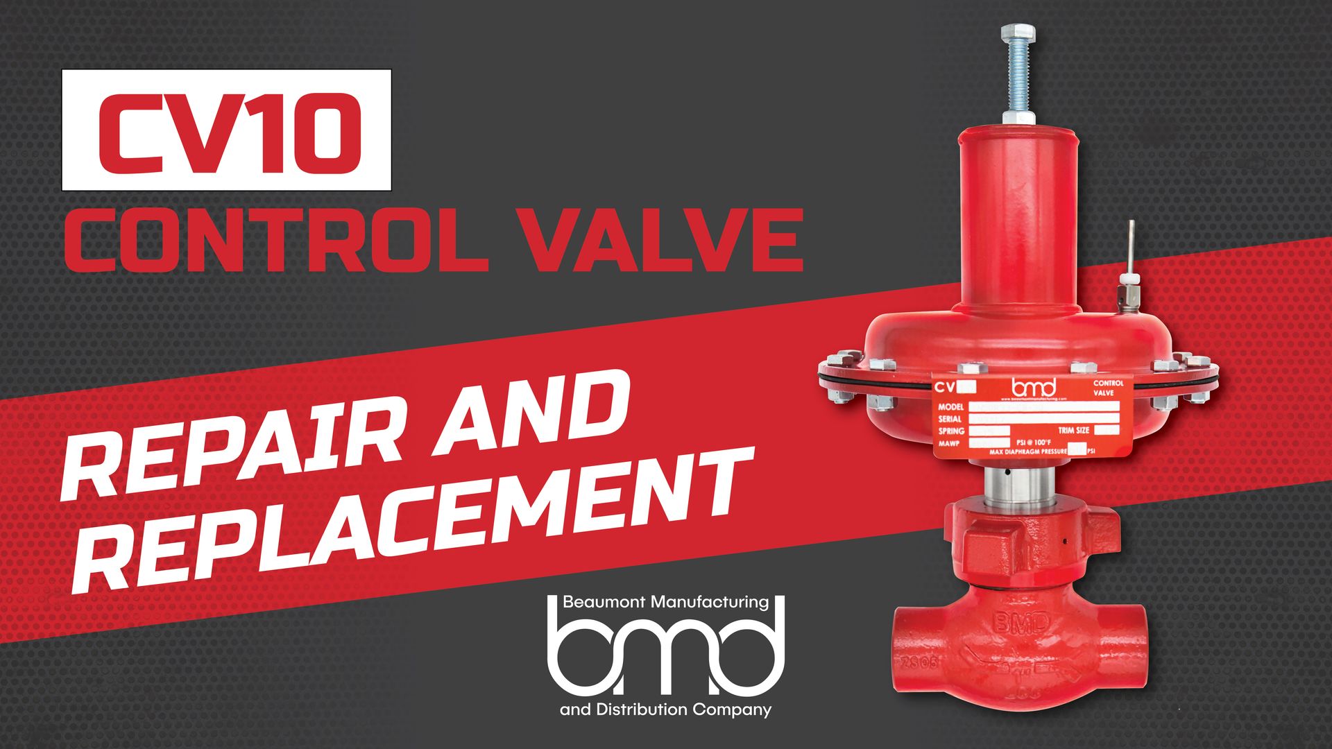
BMD Launches Repair and Replacement Series

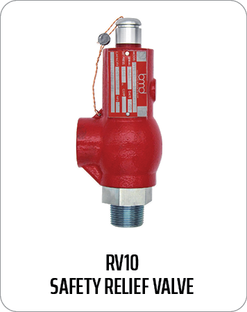
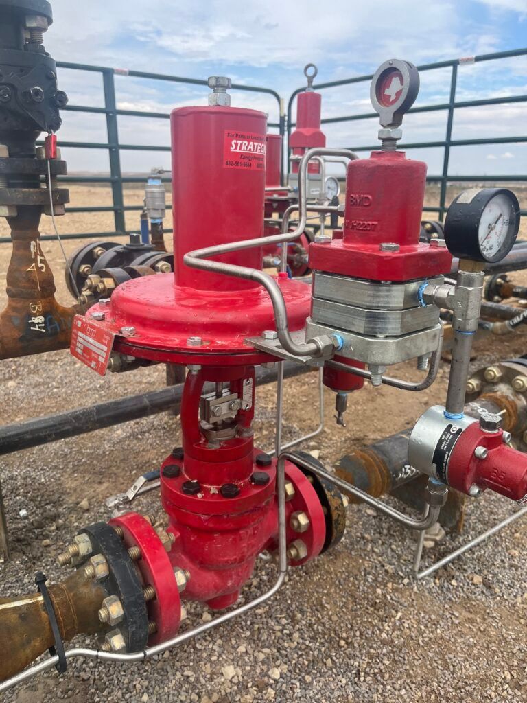
How to Maintain & Troubleshoot Relief Valves for Long-Term Performance Relief valves serve as essential safety equipment in oil and gas operations, regulating system pressures to safe levels while preventing destructive system failures. They operate as safety devices for pipelines, separators, and storage tanks throughout upstream and midstream oil and gas systems. BMD produces spring-loaded pressure relief valves that fulfill the highest requirements for durability, corrosion resistance, and reliability. However, even the most durable valves require scheduled maintenance and prompt troubleshooting to achieve optimal performance. Failing to maintain equipment properly leads to operational downtime, increased safety risks, and costly repair expenses. The following article provides instruction for relief valve maintenance and troubleshooting to ensure BMD valves operate safely and efficiently throughout their extended lifespan. Understanding BMD Relief Valves BMD relief valves are reliable and long-lasting. They can handle high-pressure systems, protecting against overpressure situations that could otherwise compromise the integrity of pipelines, storage tanks, and other critical equipment. BMD offers spring-loaded pressure relief valves that serve multiple applications across the oil and gas sector. The valves are in pipelines, separators, and storage tanks, where they protect equipment from overpressure. BMD valves surpass American design standards to deliver peak performance in demanding operational conditions. Common features include: Corrosion Resistance: BMD relief valves are designed to withstand corrosive environments commonly found in oil and gas operations, ensuring durability and a longer service life. Spring-Loaded Design: These valves provide reliable pressure relief by automatically opening when the system pressure exceeds the preset limit. American-Made Durability: Designed and manufactured in the U.S., BMD relief valves offer a high level of precision, performance, and safety. When properly installed and maintained, these valves can significantly improve the safety and efficiency of your oil and gas systems. Understanding their design and function is key to performing effective maintenance and troubleshooting. Why Relief Valve Maintenance is Critical Relief valves protect oil and gas operations by preventing overpressure, which can stop leaks, prevent equipment damage, and prevent catastrophic failures. The relief valves require regular maintenance to maintain their optimal operational state. Poorly maintained relief valves can cause various issues, such as: Worn seals or improper valve seating can result in leaks that compromise system pressure and cause safety hazards. If a valve opens too frequently or at the wrong pressure, it can cause unnecessary pressure drops that disrupt operations. Accumulation of debris or corrosion inside the valve can block the flow path, reducing the valve’s effectiveness. Regular inspection and maintenance can help detect and resolve these issues before they escalate. BMD recommends inspecting relief valves regularly based on operational conditions, including pressure cycles and environmental factors. Follow the manufacturer’s guidelines for maintenance intervals to ensure that valves perform reliably over time. Relief Valve Standards & Maintenance Recommendations BMD manufactures safety relief valves under Section XIII of the ASME code. To maintain compliance and performance, all relief valves need to be sent to a qualified VR shop for reset and recertification—this process cannot be performed by the end user. In addition, BMD strongly recommends that customers have a maintenance program in place that includes annual re-certification by a National Board certified shop holding a VR stamp to ensure safety, reliability, and regulatory compliance. Relief Valve Troubleshooting: Common Issues and Fixes Regular maintenance does not prevent relief valves from developing problems. The following section outlines typical problems together with specific troubleshooting procedures for BMD valves. The valve fails to open at its specified pressure setting. Possible Causes: Incorrect valve settings or blockage. Troubleshooting: The spring condition should be checked for wear while verifying that the valve operates at its designated pressure setting. The valve components need cleaning to remove any blockages that might exist. The valve operates at higher frequencies than expected or before reaching the set pressure. Possible Causes: Fluctuating process pressure, debris under the seat, or incorrect settings. Troubleshooting: The valve seat should be inspected for debris while verifying that the pressure settings match the specifications. The necessary adjustments or replacements should be made to the components. The valve develops leaks after its activation. Possible Causes: Seat wear, seal damage, or improper reassembly. Troubleshooting: The internal components need replacement or reseating according to the situation. All parts need correct alignment during reassembly to stop leaks from occurring. Audible chattering or vibrations. Possible Causes: Back pressure, poor mounting, or improper valve sizing. Troubleshooting: Check both the mounting and installation procedures and backpressure conditions. BMD provides installation guidelines which help users select appropriate valves and determine correct flow sizes. Long-Term Performance Tips for BMD Relief Valves The following best practices will help you achieve long-term performance: Create a maintenance schedule that considers operating conditions and manufacturer recommendations. Maintain detailed documentation of all maintenance work, inspection results, and replacement records. Technicians should receive BMD-specific maintenance training to perform proper care of the equipment. The use of OEM parts for all repair and rebuild operations will preserve both performance and reliability. Send the valve to BMD for factory service or certified testing when issues persist or when the valve exhibits significant signs of wear. Conclusion The oil and gas industry requires regular maintenance and accurate troubleshooting of relief valves to ensure safe and reliable operations. BMD relief valves are built to withstand demanding conditions, but their long-term performance depends on regular maintenance. The maintenance and troubleshooting guidelines in this guide will help you maintain relief valve reliability, which leads to better system safety and compliance, along with operational efficiency. For further assistance with OEM parts or technical support, contact BMD.